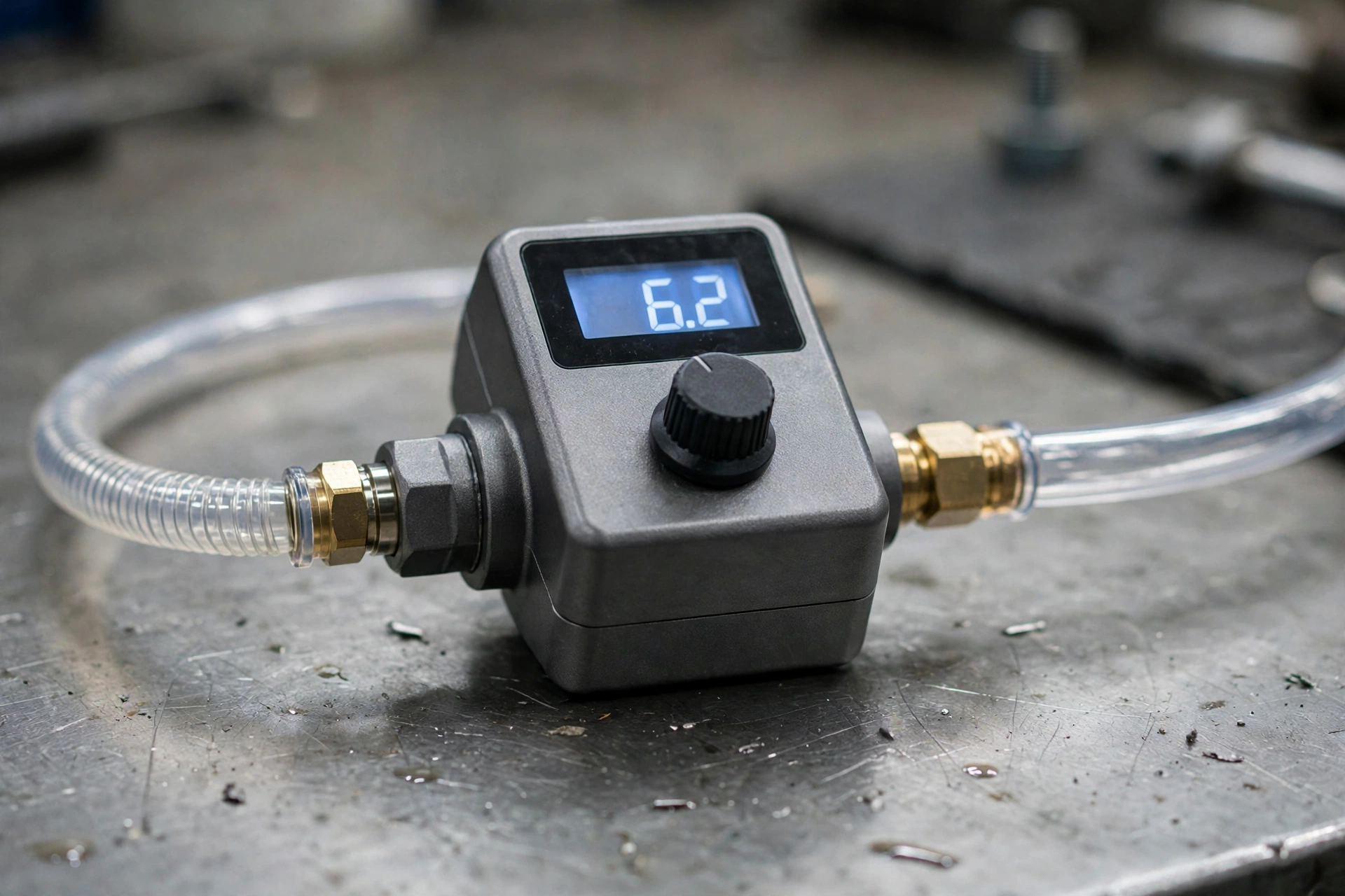
An electronic pressure regulator, often called an electropneumatic pressure regulator, is a device that converts an electrical command into a proportional outlet pressure. In plain terms, you tell it what pressure you want by sending an electrical signal, and it adjusts the air or gas pressure coming out of it to match that request, holding it steady even when conditions upstream or downstream change. That is very different from a manual regulator, where you turn a knob and hope the pressure stays where you set it, because an electronic regulator keeps measuring, comparing and correcting itself while it works. If you work with pneumatics, automation, test equipment or controlled gas handling, understanding this closed-loop behaviour is the key to using the device well.
This guide explains how to understand the electronic pressure regulator without assuming you already know control theory. It starts with the basic idea of a command signal and an outlet pressure, then looks inside the device at its sensor, electronics and valves, then explains the three broad design approaches you will meet in catalogues, and finally covers where these regulators are used, how to choose one, and the safety checks that should never be skipped. No specific industry certification is claimed here, because suitability depends on the exact model, media and application, and the manufacturer’s datasheet for your chosen unit is always the final authority.
The Basic Idea: Command In, Pressure Out
At its simplest, an electronic pressure regulator takes two things: a supply of compressed air or gas at a higher pressure, and an electrical command that represents the pressure you want at the outlet. If the command rises, the outlet pressure rises in proportion; if the command falls, the outlet pressure falls. That proportional relationship is what makes the device useful for automation, because a controller, PLC or computer can change pressure smoothly and repeatably simply by changing a voltage or current, rather than asking a person to adjust a knob and watch a gauge. A test rig can therefore step through pressures automatically, a coating line can adjust spray pressure for different products, and a pneumatic actuator can apply different forces without manual intervention.
The most common command signals are analogue: typically 0–10 V DC or 4–20 mA, with 1–5 V DC also used on some models. The 4–20 mA current loop is popular in industrial settings because it is less sensitive to electrical noise over long cable runs and because a reading below 4 mA can indicate a broken wire, while a voltage signal is simple and easy to generate from many controllers. Some modern models also support digital buses such as EtherCAT, PROFINET, PROFIBUS, Modbus and CANopen, which allow the regulator to be addressed on a network, monitored remotely and integrated into a larger automation system. Whichever signal your system uses, the important point is to match the regulator’s input type to your controller, because a voltage-output controller cannot directly drive a current-only input without the right interface.
Inside the Device: Sensor, Electronics and Valves
Inside a typical electronic pressure regulator there are three core parts working together: a pressure sensor or transducer, control electronics, and one or two proportional solenoid valves. The pressure sensor continuously measures the actual outlet pressure and turns that measurement into an electrical signal the electronics can read. The control electronics, often built around a PID controller — proportional, integral and derivative control — compare that measured pressure with the setpoint represented by your command signal, and decide how far to open or close the valves. The valves themselves do the physical work: an inlet or supply valve admits higher-pressure gas to raise outlet pressure, while an exhaust or vent valve releases pressure to atmosphere to lower it.

The closed loop works like a careful balancing act that never stops. If the setpoint rises, the electronics open the inlet valve to admit more supply pressure until the sensor reports that the outlet has reached the new target. If the setpoint falls, the electronics open the exhaust valve to vent outlet pressure until the reading falls to match. When the outlet already matches the setpoint, a two-valve design can close both valves and hold pressure in a dead volume with near-zero consumption, which is efficient for sealed or low-flow applications. A single-valve design, by contrast, often uses a constant bleed, venting a small amount of gas continuously to maintain control, which is simpler but less efficient. Understanding which design you have matters for air consumption, noise and suitability for sealed volumes, so check the datasheet rather than assuming all electronic regulators behave the same way.
For a manufacturer’s explanation of the same closed-loop principle, see the Emerson explainer on how electronic pressure control works.
Response, Accuracy and What the Numbers Mean
Two performance figures appear in almost every datasheet, and both are worth understanding before you compare models. Response time describes how quickly the outlet pressure follows a change in command, and electronic regulators can respond in milliseconds, which is why they suit dynamic applications such as test cycles, rapid actuator control and processes where pressure must change quickly between steps. A manual regulator simply cannot follow that kind of command, and even a slow electronic design may be too sluggish for a fast test rig, so match response to the speed of your process rather than choosing the fastest device by default, which may cost more and use more air.
Accuracy is usually expressed as a percentage, and a figure around ±0.1% of command is achievable with a good transmitter in closed-loop electropneumatic PID designs. That figure should be read as achievable, not guaranteed for every model, because real accuracy depends on sensor quality, calibration, supply pressure stability, temperature, media and installation. Other factors such as hysteresis, repeatability and linearity also affect how closely the outlet follows the command over time and across repeated cycles. For most practical purposes, ask three questions: how accurate does my process actually need to be, how stable must the pressure remain when flow or supply pressure changes, and what does the datasheet say under conditions close to mine, rather than under ideal laboratory conditions alone.
Three Broad Design Approaches
Catalogues can be confusing because the term electronic pressure regulator covers three broad approaches that work in different ways. The first is a motor-driven manual-style adjuster, where a motor turns the adjustment mechanism of a broadly conventional regulator in response to an electrical command. This approach can be robust and familiar, but it is typically slower and less precise than a fully electronic closed-loop design, and it may be better suited to set-and-forget applications where pressure changes infrequently. The second approach is an I/P transducer, also called an E/P or U/P transducer, which converts a current or voltage signal into a pilot pressure that then drives a mechanical regulator. This is a well-established industrial method, and it can be a good retrofit where a mechanical regulator already exists, but the overall accuracy and speed depend on both the transducer and the regulator it pilots.
The third approach is the fully closed-loop electronic controller with an onboard microprocessor, which is the design most people mean today when they say electronic pressure regulator. Here the sensor, PID electronics and proportional valves are integrated into one unit, with the microprocessor handling setpoint comparison, valve control, diagnostics and sometimes digital communication. This integrated design generally offers the fastest response, the tightest control and the most features, such as adjustable PID tuning, alarms and digital feedback of actual pressure. When you compare products, identifying which of these three approaches a model uses will explain many of the differences in price, speed, accuracy and air consumption that otherwise look puzzling.
Where Electronic Pressure Regulators Are Used
Electronic pressure regulators appear wherever pressure needs to change automatically, repeatably or precisely, rather than staying fixed. In pneumatics and automation, they control actuator force, gripper pressure, air bearings and process air, allowing a machine to handle different products or adapt to changing loads without manual adjustment. In test rigs, they step through pressure profiles to check leaks, burst strength, valve performance or product durability, where repeatability matters more than raw speed alone. In medical and laboratory gas handling, they help manage controlled gas delivery, although any medical or safety-critical use requires a model specifically rated and approved for that application, and this general guide does not replace that specialist selection.
Coating and spraying is another common area, where consistent spray pressure affects finish quality, overspray and material use, and where changing pressure for different coatings or parts can improve results. Packaging machinery uses controlled pressure for sealing, forming, filling and handling delicate products, while process control applications use regulators to maintain precise pressures in lines, vessels and instruments. The unifying theme is control: if your process benefits from pressure that follows a programme, responds to a sensor, or changes between batches without someone turning a knob, an electronic regulator is worth considering, provided the media, pressure range and environment suit the chosen model.
How to Choose the Right Model
Choosing well starts with your pressure requirements, not with a brand name. First, establish the inlet pressure range your supply will actually provide and the outlet pressure range your process needs, including any peaks, and choose a regulator rated comfortably for both, with margin for supply variation. Next, consider flow capacity: a regulator that controls pressure beautifully at low flow may struggle if your application draws large or rapidly changing flows, while an oversized unit may be less precise at very low flows. Porting and connection size, mounting orientation and physical size also matter, because a regulator that does not fit your panel, manifold or enclosure will cause installation problems regardless of its electronics.
Media compatibility is equally important, as seals and internal materials must suit air, inert gas or whatever gas you intend to control, and some media require specific materials or cleaning standards. Response time and accuracy should then be matched to your process needs, as discussed above, and fail-safe behaviour should be understood in advance: what does the regulator do if power or signal is lost, does it vent, hold, or close, and is that behaviour safe for your system. Finally, consider control interface, diagnostics, environmental rating, maintenance access and total cost, including air consumption for single-valve bleed designs. A shortlist built on those factors, checked against datasheets, will serve you far better than choosing on price or headline accuracy alone.
Safety Notes You Should Never Skip
Electronic regulators control stored energy, so safety checks are not optional extras. Always check rated pressures before installation, and never exceed the inlet rating, because overpressure can damage the device, cause leaks or create a hazard downstream. Make sure the outlet rating and downstream components are also suitable for the maximum pressure the regulator could deliver, including fault conditions, and use relief or protection where your system design requires it. Before maintenance, always vent stored pressure, isolate the supply, and follow lockout procedures where applicable, because trapped pressure in a line or vessel can cause sudden movement or release even after the regulator is switched off.
Follow the maker’s manual for installation, wiring, calibration and maintenance, including correct signal wiring, earthing, filtration and air quality requirements, because contaminated or wet supply air is a common cause of poor performance and valve wear. Do not modify the device, do not use it with media it is not rated for, and do not ignore alarms or unstable behaviour, which may indicate a sensor fault, a blocked vent, a supply problem or a control tuning issue. If you are unsure about suitability for a safety-critical, medical or hazardous application, seek specialist advice and a model with the appropriate approvals, rather than assuming a general-purpose regulator will be acceptable.
Conclusion
How to understand the electronic pressure regulator comes down to one clear picture: an electrical command sets a target, a sensor measures the real outlet pressure, PID electronics compare the two, and proportional inlet and exhaust valves correct any difference, millisecond by millisecond. That closed loop is what separates an electronic regulator from a manual one, and it explains its speed, repeatability and usefulness across automation, testing, coating, packaging and process control. Choose by pressure range, flow, media, response, accuracy and fail-safe behaviour, read the datasheet for your exact model, and respect rated pressures and venting procedures during maintenance. With those habits, the device becomes a predictable, precise tool rather than a mysterious black box, and your system gains pressure control that follows your programme instead of fighting it.
If you found this engineering guide useful, you may also enjoy our beginner-friendly look at rugby positions. It is a different subject entirely, but it follows the same clear, step-by-step approach used across this site.
Frequently Asked Questions
What is an electronic pressure regulator?
An electronic pressure regulator, also called an electropneumatic regulator, converts an electrical command into a proportional outlet pressure. It uses a sensor, control electronics and proportional valves in a closed loop to hold outlet pressure at the commanded value automatically.
What signals control an electronic pressure regulator?
Typical analogue commands are 0–10 V DC or 4–20 mA, with 1–5 V DC on some models. Some units also support digital buses such as EtherCAT, PROFINET, PROFIBUS, Modbus and CANopen. Match the regulator input to your controller output before ordering.
How does PID control work in a pressure regulator?
PID stands for proportional, integral and derivative control. The electronics compare measured outlet pressure with the setpoint, then adjust the inlet and exhaust valves to close the gap. Proportional action responds to the current error, integral action corrects persistent offset, and derivative action anticipates rapid change.
Why do some regulators use more air than others?
Two-valve designs can hold pressure in a dead volume with near-zero consumption when stable, because both valves close. Single-valve designs often use a constant bleed to maintain control, venting a small amount continuously. Check the datasheet if air consumption matters for your application.
What should I check before buying one?
Check inlet and outlet pressure ranges, flow capacity, media compatibility, porting, response time, accuracy, fail-safe behaviour on power or signal loss, and control interface. Always confirm rated pressures, never exceed the inlet rating, and vent stored pressure before maintenance.